 |
 |
 |
 |
 |
 |
 |
 |
 |
 |
 |
 |
 |
|
 |
 |
 |
 |
 |
输入密码菜单页 |
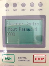 |
输入密码页面 |
|
输入正确时进入下图,否则提示“Password Error”
|
 |
|
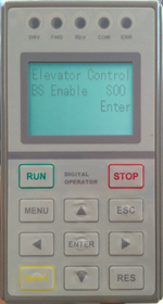
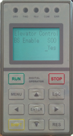
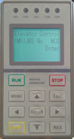
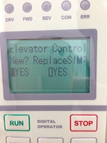
新电梯启用,选择第一个Yes有效▌(右移键切换选项),按下“Enter”然后进入新卡注册,主页面如下图;
|
 |
|
|
输入正确时进入下图,否则提示“Password Error”
|
|
|
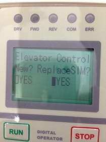
右移键选择第二个Yes有效▌,按下“Enter”进入如下图
|
 |
|
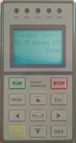
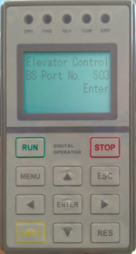
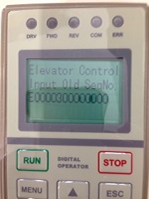
输入旧的IMSI号,旧的序列号,通过enter键和上下键输入
|
 |
旧IMSI号 |
 |
旧序列号 |
|
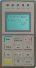
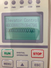
此处可以看到已经输入的旧IMSI号和序列号,如果发现输错可以通过按ESC键返回继续输入,如果检查输入没有问题,可以按下enter键发送换卡请求!
|
 |
|
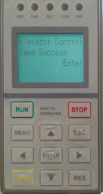
最终返回结果如下
|
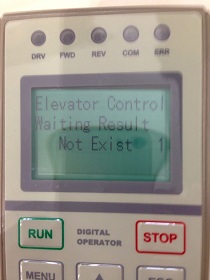 |
返回失败时如上图 |
 |
返回成功时如上图 |
|
Success更新成功:(新IMSI无论是否在平台注册过,都允许更换旧IMSI);Not Exist 更新失败(平台没有查询到旧IMSI和序列号),此时确认输入的原来电梯IMSI和序列号是否正确。一旦进入输入密码界面,必须按上述步骤完成,通过Esc或menu键不能回到主页面,用户可以通过断电设备重新启动设备或者一直按下“Esc”5秒重启设备。在主界面通过设置参数界面S01,也可以进入替换SIM界面,然后流程同上。
|
|
注:用户进行替换SIM卡时,如果用户误操作进入新梯启用,这时平台会正常注册这个卡,用户这时可以通过进入菜单Input Password,重新选择进入“RepalceSIM”完成替换SIM卡流程。
|
|
主页面显示的补充说明:
|
|
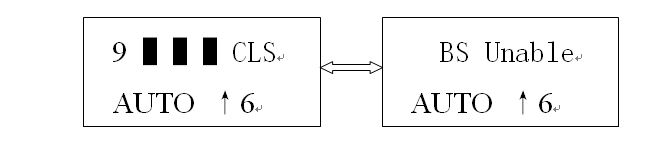
在流量小于20K时,用户可以通过参数设置” BS Enable”为“NO”关闭数据通讯, 设为“YES”开启数据通讯,大于20k时,用户不能关闭数据通讯了。
另外对于关闭数据通讯时,主页面显示如下图1秒交替显示:
|
 |
|
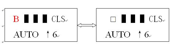
另外对于启动通讯没有到达20k时(注意恢复出厂值时,通讯流量计数清零,但实际sim卡流量运营商不会清零),如下图进度显示位置为字符与‘□’交替显示如下图:
|
 |